Linux Flash for Newbies - The Next Generation: UBI and UBIFS
The latest and greatest in Linux-MTD is UBI and UBIfs. It is important to keep in mind that UBI is not the same as UBIfs. These two are actually two layers in a stack.
UBI
UBI (unsorted block images) is an abstraction layer that rides on top of MTD. While MTD directly shows all physical characteristics of the underlying device (eraseblock size, bad blocks, etc), UBI does two important things: it shows logical blocks that are mapped in an arbitrary and not necessarily constant way and hides bad blocks from upper layers. Additionally, UBI provides a way of defining volumes inside the same MTD partition, not unlike what LVM does for block devices.
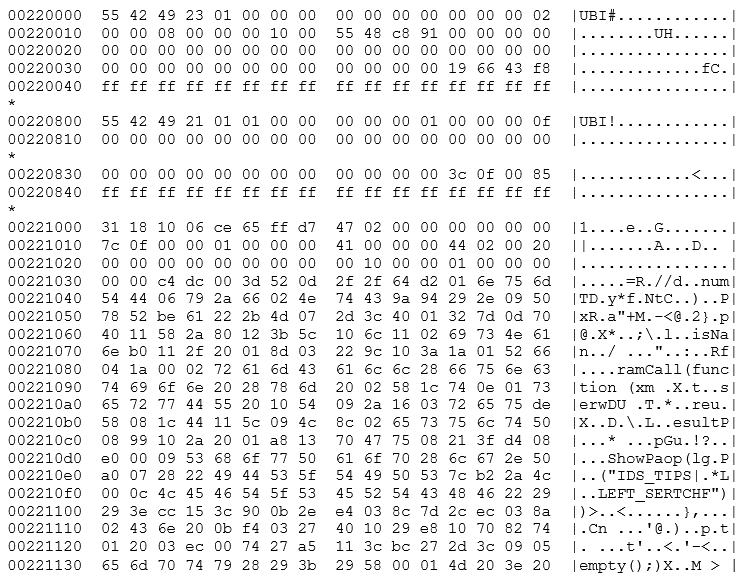
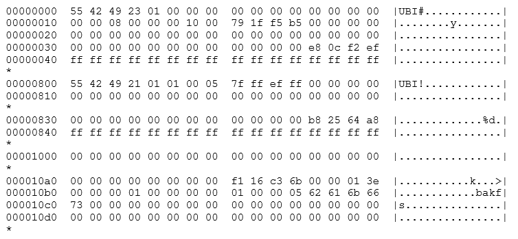
First, let’s define logical eraseblocks. UBI takes the eraseblocks presented by an MTD and adds at least one UBI header on each. This header describes, among other things, how many times it has been erased, which is essentially how badly worn it is, and what it is being used for. These headers take space, so each logical eraseblock is slightly smaller (usually by two r/w blocks of 1KB each). A second header is added once the eraseblock is assigned to a volume, describing the volume related data. Additionally, a few logical eraseblocks are reserved for volume data and as spares. Below we show a hex dump of the first blocks of a logical eraseblock. The block starts at offset 0x220000 of the flash memory, which is physical eraseblock 17. At the beginning of the block we can see the UBI erasecounter header (indicated by UBI#) which contains the logical eraseblock information. This header describes how worn the eraseblock is, adds an error detection code, and points to the next header.
Next, you can see the volume header (here at offset 0x220800, 2048 bytes into the eraseblock). This header can be recognized by the UBI! string and describes which logical volume (which will be addressed later in this guide)this header belongs to. Finally, the file system data appears at offset 0x221000, or 4096 bytes after the start of the block. This spacing of 2048 bytes is not a coincidence. Each header takes one physical block as we're using NAND flash. In NOR flash, the second header would immediately follow the first instead.
Here we can see the improved capabilities we discussed above. With respect to wear leveling, we have the remapped logical eraseblocks. Each logical eraseblock contains a block number and volume ID in its header. This data enables UBI to remap any sector at will. As an example, let's assume that we're writing to eraseblock #1 of our device. With MTD, this would be mapped straight to the first physical eraseblock of the flash device. If we keep writing and erasing this eraseblock, we will concentrate our operations on this single part of the flash and eventually wear it out. If we did the same thing to UBI's logical eraseblock #1, the erase/program operation would not necessarily go to the initial physical eraseblock. Instead, UBI would select the least worn out physical eraseblock, note in the header that this block is logical eraseblock #1 and then write the data to it. Whenever we request logical eraseblock #1, UBI will find the proper physical block and hand the data back to us, wherever it was stored. Additionally, if we were to repeatedly erase and program logical eraseblock #1, UBI would select a different physical block and write the new data to it. This protects the device, by preventing a single block from being overworn.
Furthermore, UBI also reserves some blocks as spares. This is used to mask errors in the device. Let's suppose that physical eraseblock #1 has turned bad due to overuse. With MTD, an attempt to write to physical eraseblock #1 would end in an error. The block is bad and should not be used, but it's up to the upper level to deal with it. UBI, on the other hand, would trap this error and select a different block for writing. No matter how many times we use our device, logical eraseblock #1 will always function properly, as long as it has spare blocks to cover for physical failures. UBI also proactively implements fixes: whenever a block is read and the eraseblock is weak—that is, it reads with errors but the error is corrected by an error correction code, UBI will try to remap the data to another physical eraseblock before it goes bad, in an attempt to preserve the data. This operation is transparent to the user, although UBI sends a warning when the spare blocks begin to run out, in a manner similar to what SMART does with hard disks.
Finally, UBI also allows users to define multiple volumes residing in a single MTD partition, much like LVM does with disk partitions. Some of the space reserved for UBI is used for listing and identifying available volumes. These volumes are resizable, so UBI is more flexible than MTD partitions.
In summary, UBI is a flash translation layer that can perform:
- Wear leveling
- Bad block remapping
- Volume management
- Limited recovery in case of power loss
UBIFS
UBIFS is a filesystem that is designed to run over UBI. We can see UBIFS as a replacement for JFFS2, as UBIFS deals with as many problems discovered in JFFS2 as possible. UBIFS was developed with resiliency and performance in mind. Since UBIFS is intended to be run over UBI, it requires a wear leveling layer. Therefore, it would be inadvisable to run UBIFS directly over a MTD partition, even if it were possible to force it to run in that way.
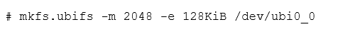
UBIFS filesystems can be either created on a mounted volume, by using it in a similar way as other mkfs programs.
Alternatively, we can use it in a mkisofs-like way, to create an image.
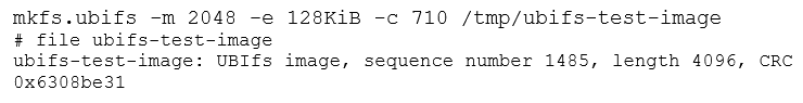
Keep in mind how we matched the eraseblock and minimum i/o unit sizes, as its importance will be discussed in the next section.
Hands on UBI/UBIFS
First, there is a matter of compatibility we have to take into account: UBI keeps erase counters on every physical eraseblock in flash. To flash UBI volumes and UBIFS filesystems we should use UBI compatible tools that preserve this data. While flashing data using nandwrite will work, this will overwrite the UBI headers as they are in the image, destroying whatever wear leveling information might be present in the flash device. By instead using UBI compatible tools, we can preserve this data, and give better tools to UBI to determine which blocks are bad and which aren't.
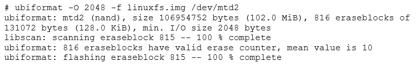
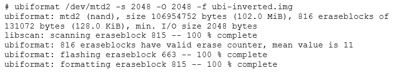
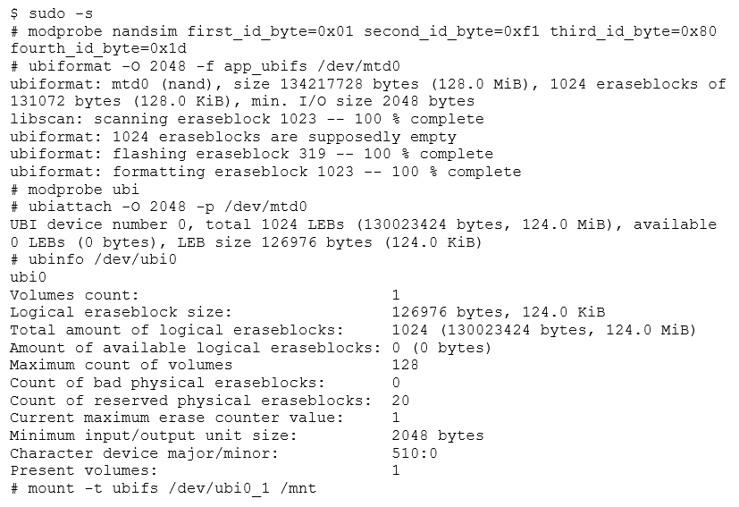
Before we start, we should format the MTD partition, as the UBI administrative data must be prepared before we can attach it to UBI. For initialization of our linux data partition, we'll use ubiformat.
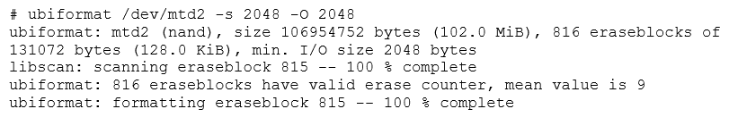
Once completed, there is now a properly UBI-formated partition. Keep in mind that ubiformat does more than erasing and formating MTD partitions. It can also write UBI images using the -f parameter, effectively flashing them into the device while keeping all the wear leveling information intact. Conversely, with the -e parameter we can manually alter this wear leveling information. Later, we'll discuss the difference between UBI and UBIFS images.
In the example above, we can see that the device was lightly used, with a mean erase counter of 9. Also, we specified the -s and -O parameters, to prevent the use of sub-pages. The -s parameter orders the operating system to use one 2048 block as the minimum unit for programming the device. Had we omitted this parameter, the kernel would have used 512 byte sub-pages as the minimum unit. This can be problematic, as the kernel has no way of telling this information to user-space tools.
The -O parameter indicates the offset of the second header (the volume header) in each eraseblock. The current conventions indicate that for NAND flash, the first header (with the erase count) should be stored at the beginning of the eraseblock, with the second header (with the volume data) in the next I/O unit (in the next page or subpage). We should know these two parameters for flash devices and UBI images, as matching those parameters between image and device are essential for compatibility.
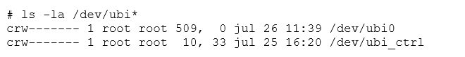
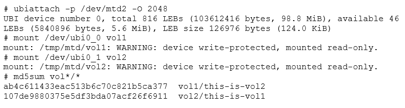
Once the partition is formated, we can attach it to the UBI system using ubiattach.

This tells the kernel to treat MTD2 as part of the UBI system. Alternatively, we could have used the -d parameter to directly specify the MTD partition number. The -O parameter is equivalent to the one used in the ubiformat command. This creates a new ubi0 device, representing the newly attached partition.
With an empty UBI device, ubi0, we still need to populate ubi0 with some volumes using ubimkvol.
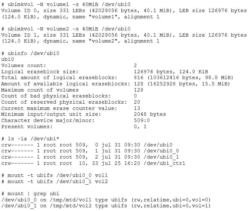
We now have /dev/ubi0_0 and ubi0_1, which represent the newly created volumes and can be mounted normally with the mount command. Remember to specify ubifs as the filesystem type. If -t ubifs is omitted, mount may report that the ubi device is "not a block device" and fail.
If we wanted to detach our newly created ubi device, we could invoke ubidetach in the same way as we did with ubiattach. For this to work, none of the UBI volumes can be mounted.
# ubidetach -p /dev/mtd2
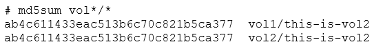
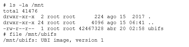
For now, let's keep the volumes attached, and add some filler data. First, we'll dump both ubi0_X devices and mtd2, detaching and unmounting as necessary. Then, we’ll review what we are left with.
After unmounting and detaching, we can extract our images quickly using dd. Since we have /dev/mtd2, /dev/ubi0_0, and /dev/ubi0_1 to dump, we will end up with three images.
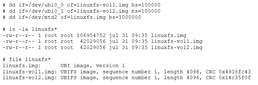
The file utility will tell us that two are UBIFS images, while the remaining one is a UBI image. This is usually a source of confusion, but having prepared the whole stack ourselves, we now know that the UBIFS images go into the UBI volumes, while the UBI image represents the partition as a whole, and should be flashed into the raw flash device. UBIFS is actually the top layer of a two-layer stack. UBI images go into the lower part while UBIFS go into the upper.
Both image types can be useful to flash a device. After attaching the raw flash, we could use ubiupdatevol to flash a new UBIFS image into a volume.
# ubiupdatevol /dev/ubo0_0 linuuxfs-vol2.img
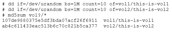
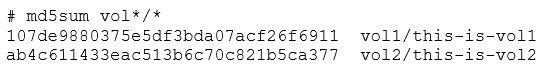
This flashes volume2's filesystem into what was volume1. After we reattach the whole stack, this is what we'll see:
The contents of volume2 have been copied to volume1, overwriting the whole filesystem. We've effectively flashed a new filesystem to a volume. UBIFS images represent volumes, just like an ISO image, or an EXT2 dump.
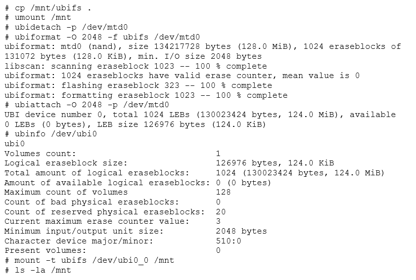
Now let's detach everything and use ubiformat to write linuxfs.img and reattach everything.
After detaching, we execute.
We then reattach and remount both volumes.
Now we're back to the original state. By flashing the UBI image, we changed all volumes in the device at once.
There is a way of converting a series of UBIFS (or other filesystem) volumes into a UBI image, for easier flashing. This is done using the ubinize program, which takes a configuration file and several UBIFS images and creates a UBI image. Let's use ubinize to create an UBI image, but with volume1 and volume2 swapped and made static (therefore read only).
First, we need to create a configuration file describing the device.
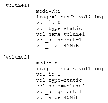
In this file, we have defined two volumes, both of 45MB size (parameter vol_size), with volume ids 0 and 1 (parameter vol_id). Since the image parameter has the UBIFS files swapped, we're going to put the contents of volume1 into the second volume and vice versa. Note how we did not consume all of the flash memory space. UBI needs some spare eraseblocks for error management, so consuming all the available space will cause the image to be unusable. Since these volumes are static and read only we could have omitted the volume sizes. In that case, ubinize would have taken just enough space for the volumes, leaving the rest as spares.
We then invoke ubinize to create an image, specifying the eraseblock size (-p) and the block size (-m), as if we were calling ubiformat.
By specifying a minimum I/O size and a subpage size of 2048, we match the parameters we've been using.

This leaves us with a UBI image containing both UBIFS filesystems inside.
We can now call ubiformat with the -f parameter to reflash our device, explicitly indicating the subpage size and volume header offset.
Let's reattach and remount everything so we can see what's in the volumes.
We have the same volumes, but now the order is inverted, and they are read only, because we declared them as static in the ubi.ini configuration file.
The Dreaded Error 22
Up to this point, we have been explicit with the minimum I/O size and the VID offset. This is to avoid the very common error 22. Below, the same steps are repeated, without being so strict about these parameters:
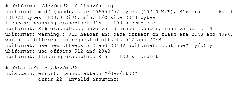
What exactly is happening here? When we created our image, we had configured our UBI system not to use sub-pages, and just to read and write in 2048 byte pages instead. We also set the VID header offset to 2048.
Recalling what we just saw while we were using ubiformat, we saw references to offsets 512 and 2048, instead of 2048 and 4096. This, plus the fact that we just altered the minimum I/O size should give us a clue of what is happening.
Let's compare an UBI image created with all parameters by default, next to an image created without using sub-pages.
Image 5: Comparative hexdump between UBI images with minimum I/O of 512 (left) and 2048 (right)
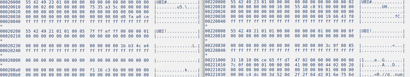
In both cases we can see a "UBI!" header at offset 0, which contains UBI's first header. However, the second "UBI#" header is at offset 0x200 in the default image, while the same header is at 0x800 in the image with explicitly defined configuration. This happens because of the way UBI handles its headers in NAND flash (in NOR flash, the second header would have been placed immediately after the first one).
NAND flash operates in pages. In some cases, some NAND devices could also operate in sub-pages. This would allow indexing in smaller units. In any case, there is always a minimum I/O unit for all operations in a specific device. Looking at the offsets, we see that the second header is at 512 bytes from the beginning in one case and at 2048 in the other.
This header placement occurs because of how UBI stores its headers. The rules for NAND state that the first header is written at the beginning of each eraseblock, immediately during format. The second header is written at the next I/O unit, but only when the eraseblock is assigned to a volume. This header has to be written on a different page or subpage, because we are doing a separate operation and don't want to disturb the first header.
The problem is that the NAND simulator allows the use of subpages of 512 bytes, which is the default. However, we created an image with the second header at an offset of 2048. The kernel attempts to attach a device and checks at offset 512 for the second header on at least one eraseblock (containing a volume listing) and finds garbage. The kernel cannot proceed and consequently returns error 22.
The second (VID) header offset is written in the first (EC) header. The kernel decides to fail to mount the device instead of just fetching the header at its indicated offset. Given that all the necessary information is present in the first header, it is unfortunate that UBI is so brittle in practice. We can see the EC header, as interpreted by the kernel, by getting a dmesg at the time of the error.
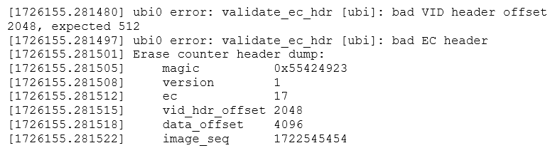
Parameter matching is a critical part of a proper UBI stack. Failure to match either eraseblock size of page size can prevent an image from being read. Always check the UBI headers and device specs for proper values, including during UBIFS image creation. Failure to do so can lead to obscure errors, like error 22 or an unmountable UBIFS filesystem.
Handling Flash Images
The key to properly mounting images is to know where they fit. The file and binwalk utilities are usually capable of identifying most common image types. When dealing with an image, these are the cardinal rules to follow.
- Images for block devices (ext2, romfs, vfat) should typically be mounted as loop devices.
- Be wary of using these (except romfs) on mtdblock devices due to the risk of ruining the flash device.
- JFFS2 images should either be disassembled with specific tools or mounted into a mtdblock device over a simulator.
- JFFS2 images should mostly be treated like ISO images, they are created whole and rarely accessed live.
- For UBI/UBIFS, the procedure depends on the exact type of image.
- Both should be run in the simulator, unless the disassembly tools work without any problems.
- UBI and UBIFS images are not the same.
- UBI images should be flashed onto MTD using a UBI compatible flasher (ubiformat).
- If it doesn't mount, use hexdump -C to locate the UBI headers to determine the memory parameters.
- The distance between UBI# headers should indicate the physical eraseblock size.
- The distance between UBI# and UBI! headers should indicate the minimum I/O size.
- The distance between UBI# headers and the filesystem data should indicate the R/W block size. If sub-blocks are used, this is the size of one block, if not then it is the size of two blocks, and the UBI# header should be right in the middle.
- UBI images may contain more than one volume. Consider dumping each volume and re-analyzing.
- If it doesn't mount, use hexdump -C to locate the UBI headers to determine the memory parameters.
- UBIFS images should be flashed using ubiupdatevol into a suitable UBI volume.
- Don’t ubinize the image, as it adds unnecessary complexity.
If what you are analyzing does not appear to be a filesystem image, analyze it with binwalk or a similar application. The image may start at an offset, or it may be a packed or encrypted file. Openssl encrypted files are common, as are tar and zip archives. If the file type is unknown, consider targeting the filesystem contents using binwalk. If you're able to read some of the contents, you can assume the file is not encrypted.
When dealing with UBIFS images, always find out the VID header offset, the minimum I/O size (usually the same as the VID offset), and the eraseblock size. Try to determine the spacing between the UBI! magic word to determine the eraseblock size, and determine the distance between the UBI! and UBI# magic words to find out the minimum I/O size. Also try to find out which type of flash device the image is supposed to be flashed to, which will lead to the datasheet, and to the proper ID bytes.
Flash Image Examples
Foscam R2/R4/C2 Firmware
For our first reversing engineering example, we'll take the firmware upgrade for a Foscam R series camera. This camera can be updated while running, so we'll take the bigger non-incremental upgrade, as the latest one is just a small patch. After downloading, we receive a ZIP file.

Let's extract the ZIP and see what's inside.
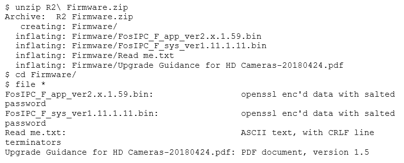
We're given some information and two encrypted files. This can be the most significant obstacle when reverse engineering a device. Fortunately, there has been some work in progress, and there is a program available on GitHub that tries several known passwords. We won't get into details, as file cracking is not the point of this post. Even after using the program to decrypt the file, we discover that the password for these files is not in there. However, after a minor modification, we can still use it anyway.
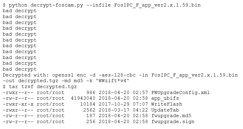
Now, we extract the contents of this file.
The archive contains an UBI image, an ARM executable (for flashing images), a device table, and some digital signatures. Seeing the digital signature, we'll know that we won't be able to tamper with a device by altering a firmware upgrade. However, these files should be useful to understand how the device works, and maybe we could locate a security issue that will eventually let us in. Let's concentrate on the UBI image.
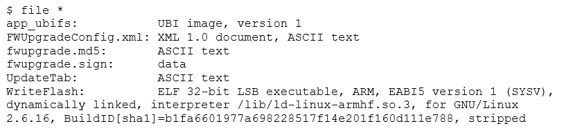
Recalling what we learned, we know we have to flash this image to an MTD partition, using ubiformat. Let's check the image first.
The Erase Counter header can be found at offset 0, the Volume header is at offset 2048 and the filesystem data starts at offset 4096. Fortunately, this is just as we were simulating. A photo of the device also shows us that the memory in question is the exact model we have been using. We can now fire up the simulator and see what's inside.
The UBI is up and running, and we now have a UBIFS volume attached and mounted. Let's check what's inside.
Instead of the root filesystem, it seems like we have another UBI image. After peeling so many layers, this looks like a Matryoshka nesting doll.

After making a copy of this file, we can keep going.
As a note, it’s always helpful to have an alternate method available, since you never know what you might come across.
Since they have been using the same parameters, we didn't have to take apart the whole stack. Volume0 is present, unlike with the other image which had volume1, meaning progress is being made This Let's check what we have mounted.
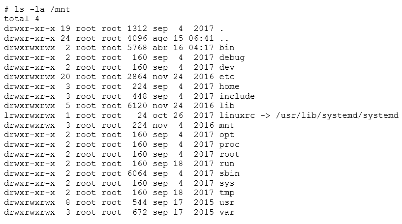
Now we've found the root filesystem. From now on, we can study this device and do a security audit on it. Now it is simply assessing the Linux system security. We could try to find something that is being executed in a flash memory, find bugs in the web interface, or read the system password hashes and go in via the console. The possibilities are endless!
Want to learn more Linux basics?
Now that you have an overview of Linux-based flash memory devices, you can keep on learning by enrolling in our Linux Security Basics eCourse.