Core Security Logo Core Security Logo
  • Contact Us
  • Support
  • All Fortra Products
  • FREE TRIALS
  • Contact Us
  • Support
  • All Fortra Products
  • FREE TRIALS
  • Cyber Threat

      Products

      • Core Impact Penetration testing software
      • Cobalt Strike Red team software
      • Outflank Security Tooling (OST) Evasive attack simulation
      • Event Manager Security information and event management
      • Powertech Antivirus Server-level virus protection
      • Product Bundles

      Solutions

      • Penetration Testing
      • Penetration Testing Services
      • Offensive Security
      • Threat Detection
      • Security Information and Event Management
    • Penetration Testing Services Security consulting services
  • Identity

      Products

      • Access Assurance Suite User provisioning and governance
      • Core Password & Secure Reset Self-service password management
      • Core Privileged Access Manager (BoKS) Privileged access management (PAM)

      Solutions

      • Privileged Access Management
      • Identity Governance & Administration
      • Password Management
    • See How to Simplify Access in Your Organization | Request a Demo
  • Industries
    • Healthcare
    • Financial Services
    • Federal Government
    • Retail
    • Utilities & Energy
    • Higher Education
    • Compliance
  • Resources
    • Upcoming Webinars & Events
    • Blogs
    • Case Studies
    • Videos
    • Datasheets
    • Guides
    • Ecourses
    • Compliance
    • All Resources
  • CoreLabs
    • Advisories
    • Exploits
    • Publications
    • Articles
    • Open Source Tools
  • About
    • Partners
    • Careers
    • Press Releases
    • Contact Us

Linux Flash for Newbies: How Linux Works with Flash

In the first series of this introduction to Linux and flash, we began with a basic lesson on flash memory. In part two, we can begin to tackle how Linux interacts with it. From this point forward, we’ll focus on NAND flash, with the following assumptions:

  • It has large eraseblocks (several tens of KB).
  • It has moderately sized programming pages (a couple of KB in size).
  • It may have sub-pages (usually 512 bytes).
  • It can only be programmed (change a one to zero) in page-sized (or subpage-sized) chunks.
  • If a bit has to be changed from zero to one, it is necessary to erase and rewrite the whole eraseblock.
  • Eraseblocks have a limited lifetime (in erase/program cycles).

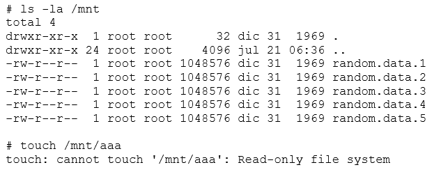
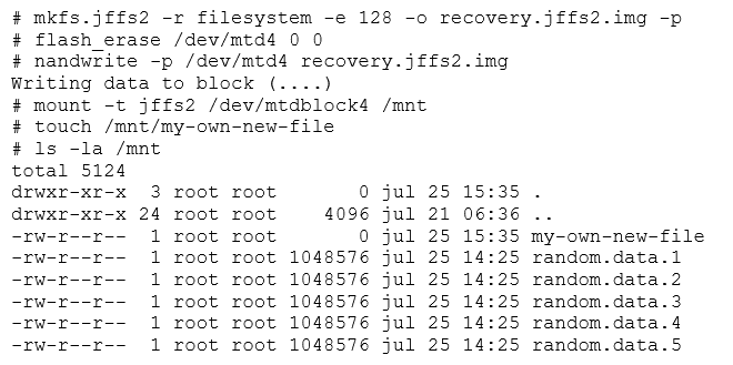
Additionally, Linux handles flash memory using the MTD modules. MTD is neither a block nor character device. Flash memory is handled in large eraseblocks, which can be erased and programmed as a whole. This poses certain difficulties in its handling. It is not possible to use traditional filesystems (like ext2), because flash does not provide a per-block (small sized randomly addressable) access. This means you are limited to erasing a full block, and cannot erase part of one.

Building a Basic Linux Flash Device

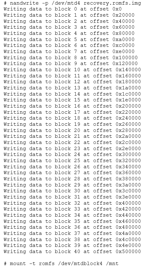
For this exercise, we'll use Linux's NAND simulator, a module that lets you repurpose a part of the RAM as if it were a flash device. This is very useful for testing and practicing. While this "flash" memory will be volatile, there won't have any problems with degradation and the simulator can be used anywhere Linux runs. Eventually, we'll learn to save our own images, so volatility won't be a problem.

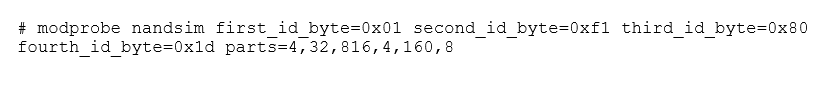
The NAND simulator can be activated by loading the "nandsim" module into the kernel. This can be done by running modprobe as root. In the example below, we're simulating a specific flash device.

Image
modprobe nandsim
 
Related Content
Article
Linux Flash for Newbies: Flash Memory Basics
Article
Linux Flash for Newbies - The Next Generation: UBI and UBIFS
Linux Penguin
Guide
Linux Security Tips and Tricks eCourse

Text

The simulator determines what to simulate based on the device's ID bytes. These bytes describe the manufacturer, characteristics, eraseblock size, and total memory size of the device. These values should be obtained from the flash memory datasheet. In our case, we're simulating a Cypress (AKA Spansion) S43ML01G2 1Gbit NAND flash, with 128KB eraseblocks. That gives us 128MB of space to work with. These id bytes are seen in the xxx_id_byte parameters passed to nandsim.

In the example above, we also passed the "parts" parameter. This tells the simulator to partition the flash device into multiple /dev/mtdN device files. Using a real flash device, this partition data would be passed to the Linux kernel on startup. Partitioning the flash device is useful to segregate different parts of the device, minimizing risk.

Let's assume we put everything in the same MTD partition. During an update, we would be reflashing the whole device, including the bootloader and the Linux kernel. One stray erase, a power failure or just writing to the wrong block could overwrite a vital part of our system and make it completely unusable.

Conversely, if we use different MTD partitions we would only be writing to the application partition, leaving the kernel and bootloader untouched. A power failure may still corrupt the system, but we might be able to use the initial bootloader to recover the system using TFTP. Had we flashed the whole device, we would probably have bricked it, without chance of recovery.

MTD partitioning is very common, and most bricked devices can usually be recovered if access to the serial console is gained. While this does not concern us in this exercise, we should still take it into account when determining how we will partition our fictitious device. The parts parameter lists each partition's size. If free blocks are left, these are allocated to a final partition. For our device, we would like the following partitions:

Image
MTD function table

Text

This partition set up mimics a typical device. There is a system boot partition, where the bootloader (usually uBoot) resides, and which we'll rarely touch. There is a partition for the Linux kernel, as well as a large partition to hold its filesystems. Additionally, there is a second bootloader, a recovery system (which would run if the main system is unbootable), and a non-volatile configuration storage. While we won’t populate these with real data, this set up is so common that we will  likely to see similar structures when we reverse engineer real systems, so it is important to become familiar with it.

Once the simulator (or a real flash driver) is loaded, we can read /proc/mtd to see the status of MTD.

Image
cat proc mtd

Text

Note how we have the same structure. The size and erase size are in hexadecimal. For example, 20000h is 128K in decimal. Additionally, the total size divided by the erase size yields the number of eraseblocks we wanted.

We can also see what has changed in our system.

Image
ls la dev mtd

Text

For each MTD partition, the system created a /dev/mtdX and a /dev/mtdXro device. These are the read/write and read-only version of each. Let's read the NVRAM partition:

Image
dd if

Text

The partition is full of ones, as would be expected in a fully erased flash device. Using dd, we can read and create images of an MTD partition. It’s important to keep in mind that although these devices appear as character devices, they are really MTD. We can reliably read them, as read is one of their primitives, but writing to them using dd is likely to be unreliable. Ideally, we shouldn't use dd for flash input/output. Therefore, we should use a flashing tool to write to them, and a dump tool to extract images from MTDs. The mtd-utils suite provides us with a series of tools to handle flash memory. In particular, we're going to use nandflash and nanddump to interact with the flash device.

Let's take some random data and put it in a file and treat it as our simulated bootloader. We can flash it, reread it and then compare it with our original.

Image
dd if dev urandom

Text

Finally, we can erase a flash device with the flash_erase command. This command is used to erase specific eraseblocks within an MTD partition, by selecting a starting block and count. This command is most commonly used to erase whole partitions, by selecting zero as the start block and zero as the count, passed in that order via the command line. This is what normally happens on many devices when the user does a factory reset. Let's see flash_erase in operation by erasing our bootloader partition.

Image
flash erase

Text

With three basic commands we are able to read, write, and erase an MTD. We should keep in mind that since READ is a valid directive, we can use dd in a pinch to dump /dev/mtdX. This will work just fine, unless the device has bad blocks, which can no longer be written to or read.

MTDBlock devices

So, what can we do with /dev/mtdX, considering that they are neither pure character devices nor pure block devices? To mount a filesystem, at least in the traditional sense, we need a block device, so how can we get one out of MTD?

The answer to all of these questions is to utilize the mtdblock module. This module converts a regular MTD into a block device, in the crudest way possible: blocks are mapped to parts of eraseblocks and for every write operation, the eraseblock is erased and rewritten. There are some clear problems with this process. A  one byte write operation could end up writing a full eraseblock (in our simulator, that would be 128KB). Additionally, there is no wear leveling whatsoever and the blocks are linearly mapped. If we write 10 times to a file, one byte at a time (assuming we let the kernel flush the data after each write), we'll end up erasing and reprogramming the eraseblock 10 times. Repeating this erase/program cycle will eventually wear out the eraseblock, and then the error will not be recoverable. Eventually some bits will become stuck and the filesystem will be corrupted.

There are several strategies to prevent this outcome. First, we could treat our filesystem as read-only and mount a ramdisk and map it to the parts of the filesystem that are variable. Older devices tend to do this, usually loading a flash-stored RomFS and copying some specific data to a ramdisk during system startup. The system runs mostly on RAM, and all data is discarded after a power cycle. User specific configuration is usually stored in a different flash partition. In our simulated system, that would be /dev/mtd5. This system organization has the advantage of being extremely durable (the flash is hardly written at all) and the flash device may even be set to read-only (preventing even accidental erases), but filesystem design is more complex because of the need to copy parts of it to RAM.

From a security perspective, RomFS systems tend to be hard to attack, because although they may have vulnerabilities that let attackers gain a shell, it would be almost impossible to modify them in a permanent way. This prevents persistent backdoors, since the system reverts to its original state after each reboot. Short of flashing a new RomFS image, a threat actor would have to resort to attacking the system once more using the original vulnerability after each reboot. On the other hand, patching is more complicated, so vulnerabilities are not taken care of as quickly. So an attacker may find it easier to keep control of the device, using the same attack to regain control of the device.

RomFS images can be generated using genromfs, in a way similar to creating ISO images. As an example, we've generated five 1MB random files, simulating our recovery filesystem. We then generate a RomFS image, which we flash to the recovery partition (mtd4). We also must pad the filesystem to a multiple of the eraseblock size by using the -p parameter.

Image
ls la filesystem

Text
Image
writing data to block

Text
Image
ls la mnt

Text

Note how the system is read-only. Our simulated system would have to copy any data that needs to be variable to the RamFS. This is usually seen as a series of cp commands in the initial system boot scripts (like rc.local).

A different strategy consists of using a medium aware journaling filesystem, like JFFS2. This filesystem is mounted directly over mtdblock and contains enough information about the flash device to know where to write the new information in a way that more evenly distributes the wear between different blocks, to avoid wearing out a specific one. The filesystem also has to deal with bad blocks by itself.

The procedure is similar to what was done with RomFS, just using mkfs.jffs2 instead. In this case, the size of the eraseblock is passed to mkfs.jffs2, as it needs to know the eraseblock size to organize its own journals. Unlike RomFS, the filesystem can be written to.

Image
mkfs jffs2

Text

This mostly done in second generation devices. These devices now have a read/write root filesystem, so bootstrapping is simplified. The system can even be patched while it is online. This has both advantages and disadvantages. Security patching is simplified, but an attacker can also easily gain a foothold into the system by modifying the boot scripts.

Finally, while it is perfectly possible to use a regular filesystem over mtdblock, it is strongly discouraged. A file can be created and mkfs is utilized to create a regular filesystem. But flashing and mounting the file as we did before will destroy certain eraseblocks (mainly those containing filesystem structures) and will likely cause subtle errors, until it fails catastrophically.

Continue onto the next article in the series, The Next Generation: UBI and UBIFS.

How Secure is Your Linux Environment?

CTA Text

Enroll in our Linux Security Tips and Tricks eCourse to learn how to make sure your Linux systems have a solid foundation of security.

ENROLL NOW
  • Email Core Security Email Us
  • Twitter Find us on Twitter
  • LinkedIn Find us on LinkedIn
  • Facebook Find us on Facebook

Products

  • Access Assurance Suite
  • Core Impact
  • Cobalt Strike
  • Event Manager
  • Browse All Products

Solutions

  • Identity Governance

  • PAM
  • IGA
  • IAM
  • Password Management
  • Vulnerability Management
  • Compliance
  • Cyber Threat

  • Penetration Testing
  • Red Team
  • Phishing
  • Threat Detection
  • SIEM

Resources

  • Upcoming Webinars & Events
  • Corelabs Research
  • Blog
  • Training

About

  • Our Company
  • Partners
  • Careers
  • Accessibility

Support

Privacy Policy

Contact

Impressum

Copyright © Fortra, LLC and its group of companies. All trademarks and registered trademarks are the property of their respective owners.